
Morris Minor - fuel gauge
Symptoms of problem : Fuel gauge not working or working only at times.
Vehicle : 1957 Morris Minor 1000 Pick-up (LCV) - a CKD MM built in Petone, New Zealand. (part Series II, part Minor 1000 I think!)
Time : 2 hours or more Difficulty : 4/10 Parts required : replacement fuel gauge ? , replacement tank sender unit (£22) ?
Special tools required : Digital or analogue voltmeter + ohm-meter and/or 12V test bulb with 2 flying leads and crocodile clips.
Description : The MM fuel gauge is a very basic circuit - a series circuit - the tank sender unit mounted in the tank is a variable resistor with a float attached, which controls the flow of current in the circuit - this current is then measured/read by the speedometer-mounted fuel gauge. A full tank raises the float and lowers the resistance, causing a greater current to flow, which is read as 'Full' by the fuel gauge, which is actually an ammeter (measuring the current flowing). An empty tank causes the float to be at its lowest position, which is the highest resistance position, which in turns causes the smallest current to flow, which registers as 'Empty' on the fuel gauge. The fuel gauge is mechanically damped, which means the pointer moves slowly to give a correct reading and does not waggle around as fuel sloshes around the tank. (Note : later versions of the circuit below have a 'Instrument voltage stabiliser' between the fuse and the fuel gauge - this will need to be tested as well as the rest of the tests described below)
Problems : The tank sender unit is mounted on top of the fuel tank and is prone to rusting and corrosion - water tends to lie in a pool on top of the sender unit and rusts it slowly over time. The electrical connection to this sender unit can also corrode, causing either the wire to fall off or the connector to fall off. In both cases the fuel gauge will stop working because the 'series' circuit is broken. The wiring from the front of the vehicle to the tank is also vulnerable in places and can break or be damaged. Older wiring can often look OK, but be 'high resistance' inside which can make faults difficult to pinpoint.
At the fuel gauge end of the circuit (in the speedometer) the fuel gauge itself can burn out, or 'short-circuit', or become 'sticky'.
Repairing the fuel gauge
You may need to remove the parcel shelf, glove compartments or whatever is necessary to get at the rear of the speedometer.
CAUTION : Make sure you disconnect the battery (one terminal is all you need to disconnect) if you need to unbolt the speedometer and move it out of the dashboard (yet still connected to most of the wiring) for your fuel gauge tests - it is very easy to cause a 'short-circuit' which could damage something, blow a fuse or cause a fire. Only reconnect the battery when you are sure that all the wiring is not near the surrounding metalwork. You will need to disconnect the speedo drive cable and pull out some of the warning lamp holders from the speedo to allow you to move the speedo far enough out to get at the fuel gauge terminals. I'm lucky (?) that there is so little internal trim in my MM that the rear of the speedo is easily accessible.
Firstly, as with most electrical faults, you have to identify which part of the circuit is faulty - this is done in a logical way, tracing the voltage through bit-by-bit. I'll describe how to use a 12v bulb + leads as a 'tester', although a digital voltmeter makes life a lot easier (they are available very cheaply = £8 nowadays).
Start at the battery terminals by putting your test lamp straight across the terminals - it should glow brightly of course. Next, move inside the vehicle and attach one lead from your test lamp to a suitable earth point i.e. some point that is definitely well-bonded to the chassis of the vehicle - check for a good contact which is to bare metal, not painted metal. Look behind the speedometer and identify the 2 terminals (1/4in spade terminals) which are the connections to the fuel gauge. Now, switch on the ignition (for only a minute or two at a time in case the distributor points just happen to be closed) and carefully touch the other lead from your test bulb to each of the fuel gauge terminals in turn - the lamp should light up when touching either terminal, but may be brighter on the left-hand (as seen from behind the speedo) - this left-hand terminal is the one connected directly to the fuse/battery, whereas the right-hand terminal is the side of the fuel-gauge which goes to the tank sender unit.
If the lamp does not light on either terminal, with the ignition on, the fault lies in the fuse or the wiring from the fuse to the gauge. If the lamp does not light on the RH terminal, the gauge itself is faulty and must be replaced. A replacement gauge (if you can get one) is fairly easily fitted - held in place by 2 small bolts. Note that there are 'gold' and 'black' versions of the actual fuel gauge and that the needle is very fragile when exposed - don't touch it.
 'Black' fuel gauge - marked 'MM1'
Once you are sure that the gauge is OK, next check the wiring to the tank sender unit. Do this by (with the ignition on again) touching your test lamp between the terminal on top of the sender unit (on top of the petrol tank) and a suitable good earth point.
CAUTION : Safety hazard - it is (very unlikely but not impossible) that you might have a small petrol leak from or near the petrol tank and that you could create a spark with your testing of the tank sender unit. In practice this is not likely, but take care. Make all connections and disconnect all connections with the ignition 'off'.
If the wiring from the gauge to the tank sender unit is OK, the lamp should glow, indicating that voltage (via the fuel gauge) is reaching the tank sender unit - however, depending on the amount of fuel in the tank i.e. the position of the float, the test lamp may be quite dim. Try removing the wire and connecting your test lamp from the wire end to earth - it should glow brightly.
Lastly, if the gauge and wiring check out OK as above, the tank sender unit is tested by disconnecting the wire from the sender unit terminal, and 'shorting' it to a good earth point - with the ignition on the fuel gauge should now read 'Full' under these conditions. If the gauge does read 'Full' now, but does not read at all (or gives a false reading) when the wire is reconnected to the terminal, then the tank sender unit is faulty. This is bad news because they are difficult to replace. With the wire to the gauge disconnected, use an ohm-meter to measure the resistance of the tank sender unit - measured to chassis/earth the values should be as shown below beside the photo. Recheck everything and get a second opinion from an auto electrician before replacing the tank sender unit.

New tank sender unit (MGM Spares FUL102) with cork gasket (FUL103 - sold separately) The 6 fixing bolts look like 2BA to me. (the originals had a 1/4" AF hex head with screwdriver slot) This replacement tank sender unit has a 0.25" spade terminal on the top - earlier versions used a screw/bolt to secure the wire to the gauge.
Tank empty = float at lowest position => resistance to earth = 256 W Tank full = float at highest position = 40 W (approx)
In my experience of fuel gauge faults, it is often not the tank sender unit that is faulty, but more likely the fuel gauge itself or the wiring.
I recommend coating the whole surroundings of the tank sender unit with a thick layer of black Hammerite 'Shutz with added Waxoyl' to prevent future rusting. See photo below :
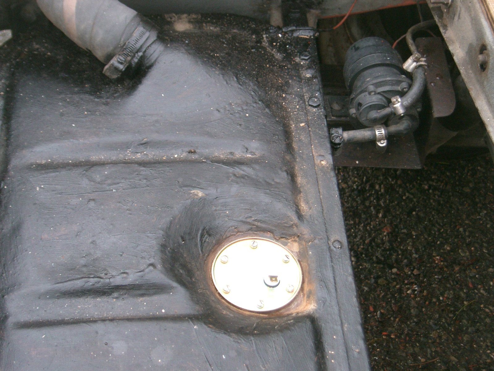
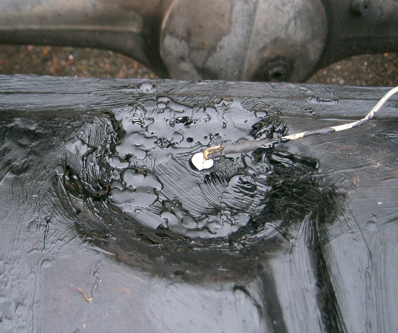
New tank sender unit installed. New tank sender unit sealed with Shutz
Note the position of the fuel pump in this LCV - next to the tank - there are 2 types of SU fuel pump - this is the 'push' type.